Raspberry Pi and Dotstar LED Jukebox
A little while ago I made a media centre for some friends, which had hardware audio playback controls. Much as I love giving people things, I was a bit jealous because it was pretty cool thing (even if I do say so myself). When the opportunity came up to make one for our upcoming wedding, I jumped at the chance, and added a few features extra to the original design. A little time scouring the internet for parts and then, time to assemble:
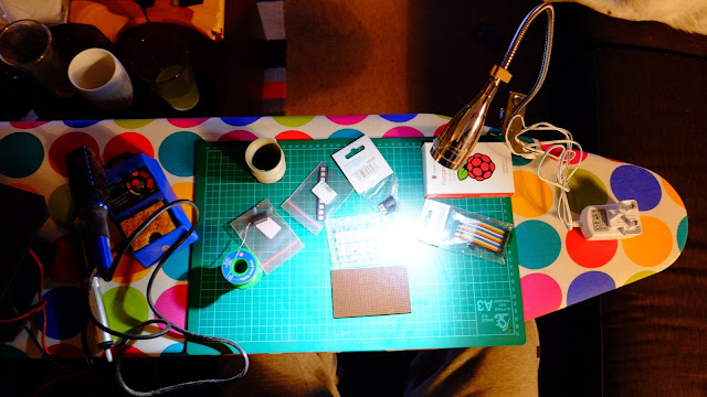
First up, out with the ironing board (soldering iron is an iron, right?). The dotstar LEDs run at 5v and the Pi's GPIO outputs at 3.3v, so we need a level shifter/bus buffer to bump the volts up a bit.
 Terrible messy circuit "diagram", but it worked. You can see the LED layout down at the bottom, there are six pins on each one - power, ground, clock in, data in, clock out, data out. This means they can be chained and addressed individually by software. They're pretty smart little things. Dotstars are new and a little more flexible than NeoPixels.
OK, bit of swearing and fixing some bad solder joints later and the leds are working. Time to make something to mount them in.
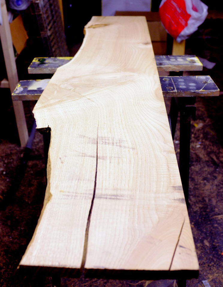
 Wood wood wood, it's better than bad it's good. Picked up a lovely bit of tulip from my local sawmill. This will be my first try at a mitre cornered box.
 Holes in the front for the switches to poke out through.
 Cutouts in the back of the front piece for the switch bodies to sit in. The wood is pretty thick but I wanted it to be a nice hefty box with some weight to it.
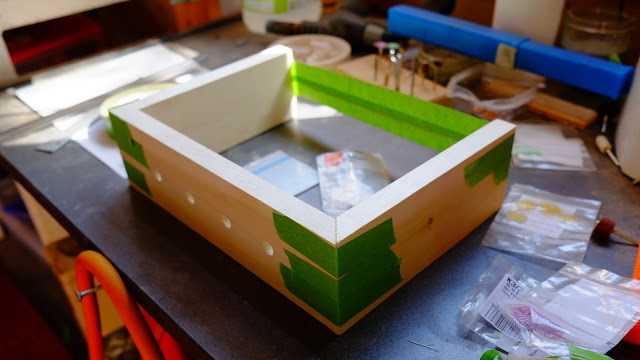 Glued and taped up. Fingers crossed!
 Shaping a piece of perspex to go inside the box. This will be edge-lit by the led strip. It's not blue, it's clear, but the protective covering is still on. Sanding perspex is unpleasant.
 Phew! Box came out OK. The back piece has cutouts for power, power switch, HDMI and audio out, and the RAVE BUTTON. I had at this point made a bit of an error. The base and the back panel were glued into place and when the top is also glued on, I won't be able to access the inside. Bad planning, but I was excited about how well the box corners had come out. Time to think of a
 bodge elegantly engineered solution.
 Meanwhile, gluing up the piece for the lid. The piece of wood I bought wasn't quite the right size so I need to join two bits together. More clamps required.
 Access solution. Cut a flap in the bottom, hinge it and hold it in place with some bits of copper. Messy, but at least it's not visible. Kicking myself for this one.
The gap between the base and the front is deliberate, however, to provide a little bit of air circulation otherwise the box would be pretty well sealed.
 Audio and HDMI port replicators glued into place. The Pi gets proper mountings, which is quite exciting - normally, I just bodge these things in. I have never ever bought a single one of these little brass mount thingys, but I have hundreds of them in my random computer screws drawer.
 Hot glue to fix down various bits. You can see some of the jumper cables attached to the Pi's GPIO pins, they're getting attached to the switches.
 Installing the switches.

Bits and pieces installed, time to glue on the perspex. A nice layer of epoxy and 24 hours under clamps. Need more clamps.
 Sanding the overhang down on the perspex was an absolute pig of a job. But it's lovely and flush now.

This was a really fun job. Gluing the leds to the inside edge of the perspex. Very satisfying.
 Last shot of the interior before gluing the top on. In the end I added a usb soundcard (black thing, roughly frame centre) that I had lying around to slightly improve the sound quality. Under the hdmi cable you can see the level shifter and power distribution board. 5V goes to the Pi, the LEDs and the hard disk separately. The external power block is a 4A switched mode supply, which is just about enough to handle the theoretical max power draw of everything. The LEDs can pull almost 2A if they're all on full power but that almost never happens.
 Last glue job. Top piece to perspex. Followed by lots of sanding, and then six or seven coats of satin finish poly varnish. Still need more clamps.
I also had to cut down the switches so they'll fit the lovely machined solid aluminium knobs I had to go on there.
 Knobs on. Awwww yeah. They've got a great knobfeel, nice and heavy but still good and positive. Very satisfying. Each knob triggers a playlist in Kodi, and if you turn on more than one knob, it creates a playlist made of a mixture of all active playlists. I've put my code for controlling dotstar leds with a raspberry pi on another post.
 Powering up, it does a little rainbow chase around the lights to let you know it's working.
 Playing. The left-most switch is on, hence the fixed-colour led above it. During playback the LEDs phase gradually through the spectrum.
 Mmmmm, yeah. So pleased with these corners. It's only right up close that you can notice the grain doesn't quite wrap perfectly around the corner.
 Rear panel. Power switch, power socket, hdmi socket (covered), audio out, rave button.

Here are the lights in action. No audio because every time I post audio to YouTube I get told off for copyright infringement even when I'm super careful to find copyright-free music tracks. Just imagine some music you like is playing. Click through to YouTube for lovely HDness.
Obligatory link to my store, where you can't buy things like this but you can buy other lovely shiny stuff.

First up, out with the ironing board (soldering iron is an iron, right?). The dotstar LEDs run at 5v and the Pi's GPIO outputs at 3.3v, so we need a level shifter/bus buffer to bump the volts up a bit.

OK, bit of swearing and fixing some bad solder joints later and the leds are working. Time to make something to mount them in.


The gap between the base and the front is deliberate, however, to provide a little bit of air circulation otherwise the box would be pretty well sealed.


Bits and pieces installed, time to glue on the perspex. A nice layer of epoxy and 24 hours under clamps. Need more clamps.


This was a really fun job. Gluing the leds to the inside edge of the perspex. Very satisfying.


I also had to cut down the switches so they'll fit the lovely machined solid aluminium knobs I had to go on there.


View from the top. That tulip is so pretty.
Here are the lights in action. No audio because every time I post audio to YouTube I get told off for copyright infringement even when I'm super careful to find copyright-free music tracks. Just imagine some music you like is playing. Click through to YouTube for lovely HDness.
Obligatory link to my store, where you can't buy things like this but you can buy other lovely shiny stuff.


Are you aware of any parts that would go well with this in order to turn it into an alarm clock? Also, what're those chips that sync to another clock called?
ReplyDeleteNo parts list?
ReplyDeleteWell it's all kind of mentioned in the post. There's a raspberry pi, some switches, some dotstar leds, some bits of wood, etc.
Delete